1876 V Box Single Receptacle Wiring Diagram
Lower deadfront cover rotates 90 degrees or can be removed for easy routing of incoming wires or receptacle changeouts. Dont use this receptacle when no ground wire is available.
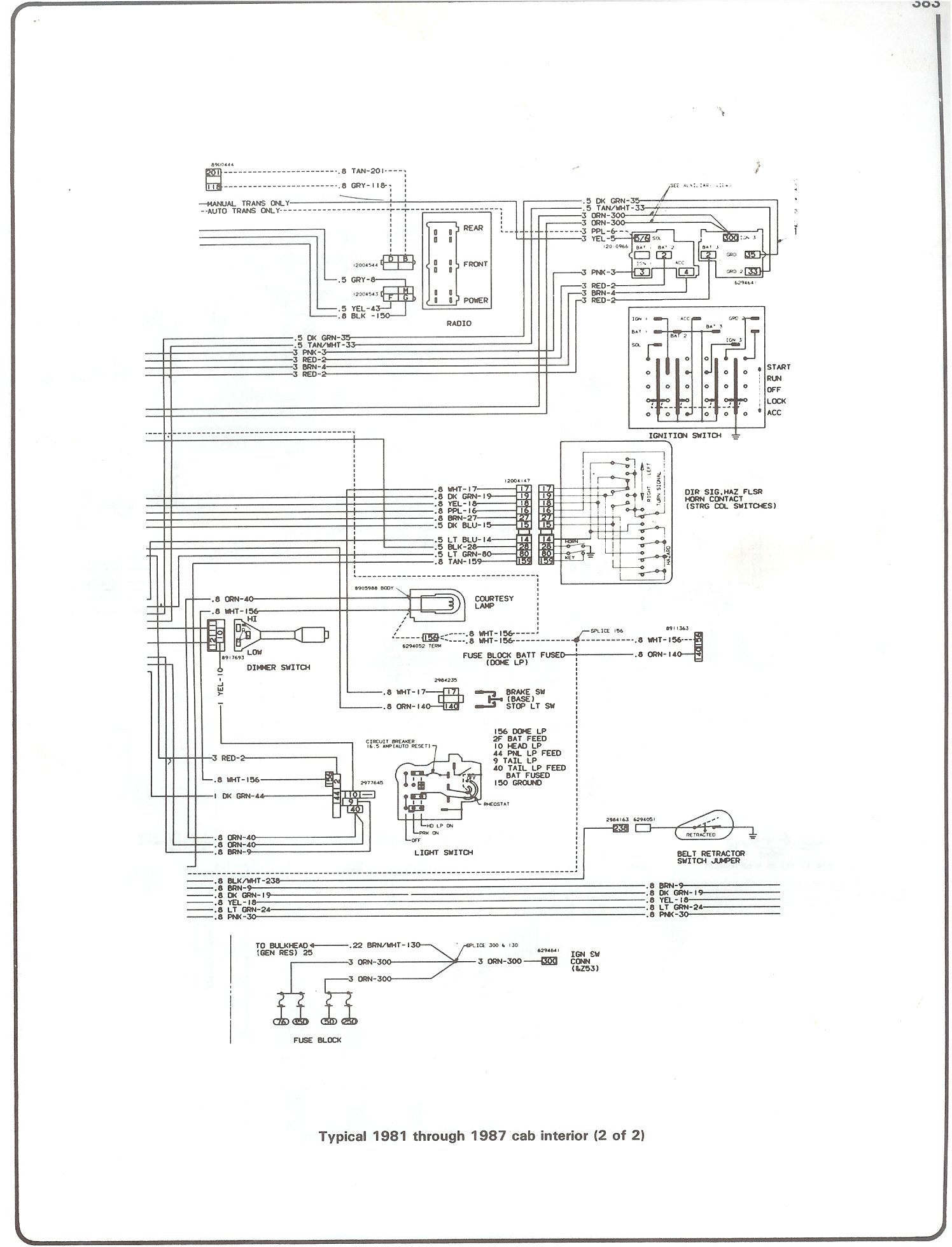
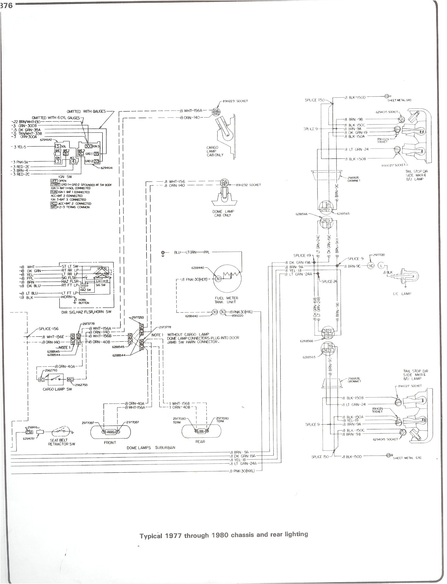
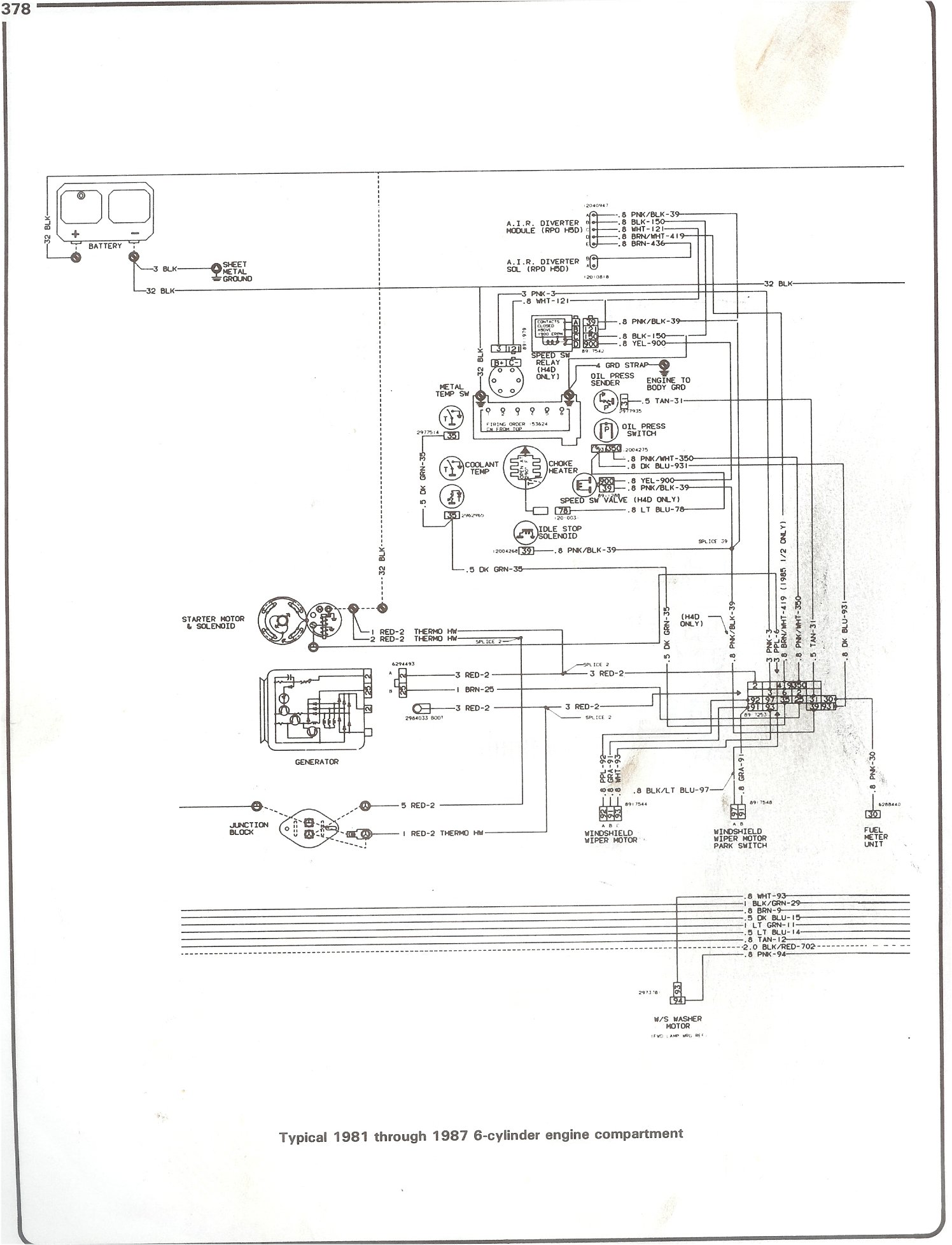
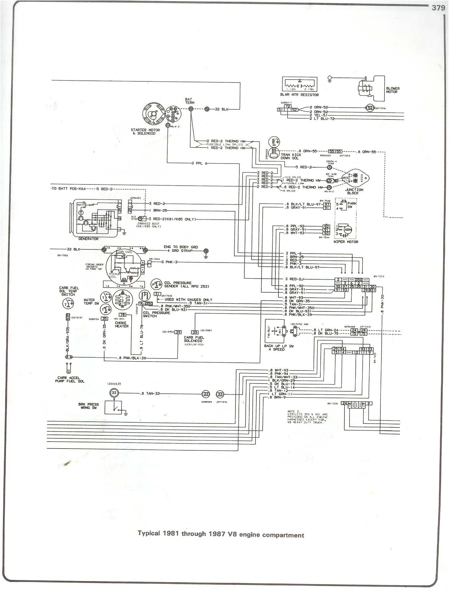
Complete 73 87 Wiring Diagrams
In-store pickup orders are not affected.

1876 v box single receptacle wiring diagram. In the wiring diagram above a hot and a neutral enter the single pole switch box. The 3 prong dryer wiring diagram here shows the proper connections for both ends of the circuit. COOPER 1876V-BOX Description 1876v Box Single 3 Wire Grnd 20a 250v.
The ground or bonding wire should be connected to the bonding screw in the device box and either pig-tailed in the case of more than one conductor or left long enough to connect to the green grounding bonding terminal on the receptacle. A switch receptacle combo is a single pole switch AND a regular receptacle that takes up the same amount of space as a regular duplex receptacle outlet. A grounded contact at the bottom center is crescent shaped.
The long slot on the left is the neutral contact and the short slot is the hot contact. Single-Speed Full-Voltage Magnetic Controllers for Plug-Stop Plug-Reverse or Jogging Duty 104 Table 16 Power Conversions 104. Wiring a Grounded Duplex Receptacle Outlet.
The same wiring diagram can be used if the power is instead coming from another outlet and connected to one of the depicted outlets on the end. From there a 3 conductor cable is installed to a switched electrical receptacle outlet. This circuit originates from the breaker box containing a 2-pole 30 Amp breaker.
Wiring Two Outlets in One Box In this diagram two duplex receptacle outlets are installed in the same box and wired separately to the source using pigtails spliced to connect the terminals of each one. Wiring Diagram for Dual Outlets. We want your transaction to be a five star experience.
1 SINGLE POLE 30-amp 120-volt Breaker 1 TT-30 Receptacle and 1 Black HOT 1 White NEUTRAL and 1 Ground Correctly sized wire The 30-amp service for an RV is 120-volt with a 3 prong receptacle and a single 30-amp dedicated breaker. This size breaker requires a minimum of a 10 gauge wire so this wire used would be a 102 with ground. When installing or replacing a receptacle connect the ground wire first.
As shown in the fig the switch is firstly installed in the wiring the hot wire from switch feeds all the other parallel connected outlets hence the outlet ONOFF operation can be controlled through the switch. This diagram shows the wiring for multiple receptacles in an arrangement that connects each individually to the source. Wiring Diagram for Multiple Outlets.
NEMA Plug Receptacle Configurations 2 pole 2 wire 2 pole 3 wire grounding 3 pole 3 wire 3 pole 4 wire grounding 15 4 wire AMP 125V 250V 125V 250V 277V 125250V 30 250V 125250V 30 250V 30 120. Switched outlet diagram with hot and a neutral entering the switch box. This is a polarized device.
1876B-BOX Cooper Wiring Devices Single Receptacle 20 A- 250 V 2-Pole 3-Wire. The following wiring diagrams show that multiple outlets are wired to a single pole SPST switch one-way or two way in US switch. Wiring Diagram Book A1 15 B1 B2 16 18 B3 A2 B1 B3 15 Supply voltage 16 18 L M H 2 Levels B2 L1 F U 1 460 V F U 2 L2 L3 GND H1 H3 H2 H4 F U 3 X1A F U 4 F U 5 X2A R Power On Optional X1 X2115 V.
This wiring allows for source voltage at each outlet independent of the others in the circuit. When removing an old receptacle disconnect the ground wire last. Compact Version Wiring Diagram.
The 30 AMP is a standard ANSI C7313 TT-30P plug TT-30R receptacle. If they are not return the item and the price of the item will be refunded. All wires are spliced to a pigtail which is connected to each device separate from all the others in the row.
14 indicates 125250 VAC single phase four wire three pole 15 indicates 250 VAC three phase four wire three pole 16 indicates 480 VAC three. This is a standard 15 amp 120 volt wall receptacle outlet wiring diagram. If they dont please let me know and I will get you that number.
Receptacle wiring diagram examples Minn Kota Trolling Motor Plug And Receptacle Wiring Diagram December 1 2018 February 15 2019 Wiring Diagram by Hadir. Due to high order volume order processing times for ship-to-home orders are currently 7-10 business days. Wiring diagrams for electrical receptacle outlets do it yourself help com 8350 50 amp nema 18 50r flush mtg in black leviton 208v single phase and 3 oem panels can i run loads with a three generator yup green mountain generators plug configurations diagram twist lock full version hd quality rediagram amicideidisabilionlus 220 volt receptacles askmediy 28w81 hubbell Read More.
Lower deadfront cover permits easy field wiring. Wiring Diagrams for Multiple Receptacle Outlets. 1876B BOX COOPER Wiring Devices Single Receptacle 20 A- 250 V 2-Pole 3-Wire - 969.
You may be capable to know exactly when the tasks needs to be finished which makes it easier for you personally to correctly manage your time and efforts. Cooper CWL1020R Ground Lock Single Receptacle 125250 V 20 A 3 Pole 3 Wire Black Arrow Hart 817 Straight Blade Single Receptacle 125 V 15 A 2 Pole 3 Wire Ivory RECEPTACLE SGL LT ALMOND 125V Cooper TR817V-BOX Tamper Resistant Single Receptacle 125 V 15 A 2 Pole 3 Wire. 3 Wire Plug Wiring Diagram Wiring Diagram Online Receptacle Wiring Diagram In addition Wiring Diagram gives you the time body in which the assignments are for being accomplished.

Understanding 240v Ac Power For Heavy Duty Power Tools Make Outlet Wiring Ac Plug Trailer Wiring Diagram
Complete 73 87 Wiring Diagrams
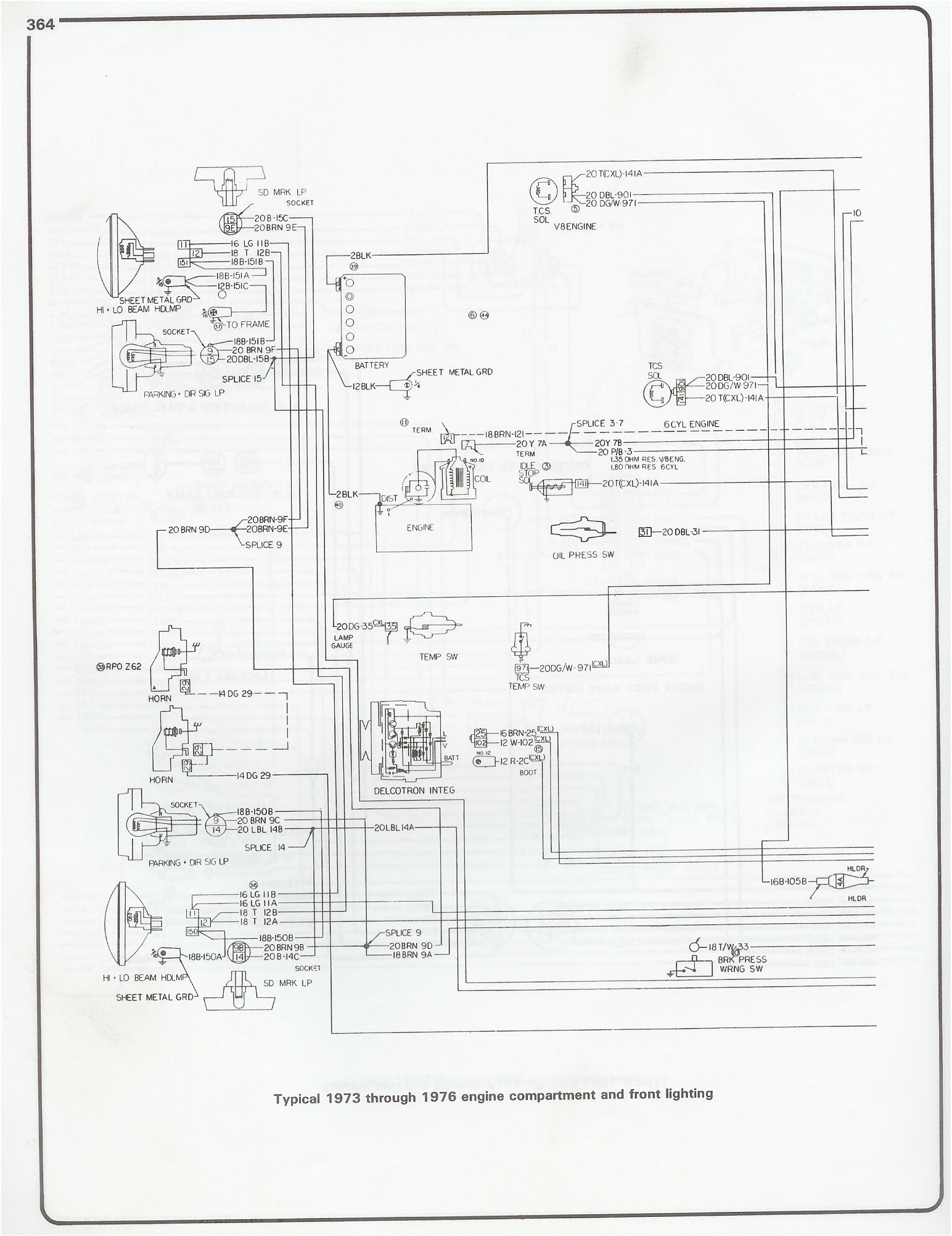
Complete 73 87 Wiring Diagrams
1876w Box Eaton Commercial Specification Grade Single Receptacle Eaton

Wiring Diagrams For Electrical Receptacle Outlets Electrical Wiring Outlet Wiring Home Electrical Wiring
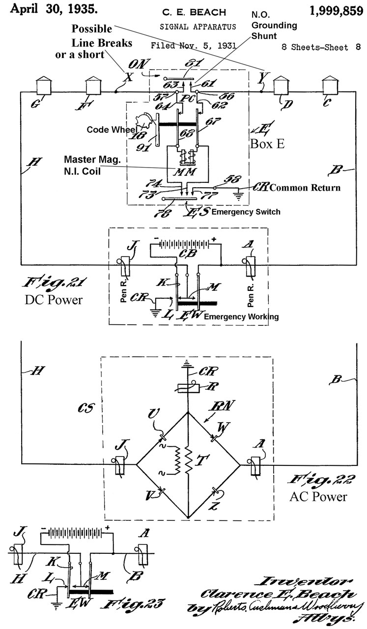
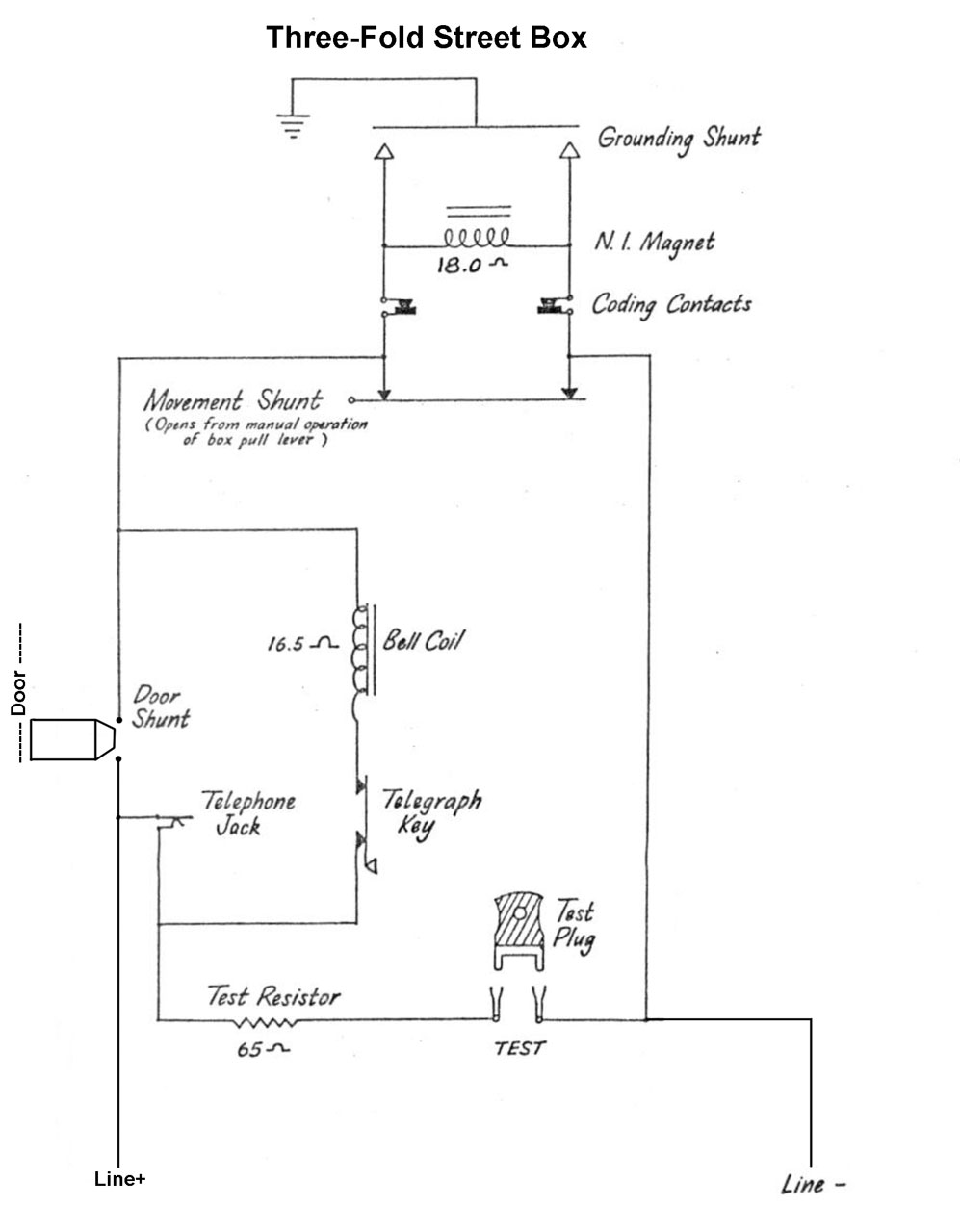
Gamewell Fire Alarm Box

Using Wire Connectors Connect The Two Hot Wires Of The Power Cable To Their Respective Thermostat Wires Refer To Wiring Water Heater Heater Thermostat Wiring
Complete 73 87 Wiring Diagrams

Swartz Electric Colorado Springs Highest Rated Electrician History Of Electricity Science Electricity Electricity

Electrical And Wiring Diy Electrical Outdoor Electrical Outlet Diy Outdoor

Dyna 2000i Ultima Programmable Single Fire Electronic Ignition Module American Classic Motors
Diagram 2010 Jeep Wrangler Transmission Wiring Diagram Full Version Hd Quality Wiring Diagram Diagramthefall Martamenegatti It


Wiring Diagram 3 Way Switch Unique Wiring Diagram For Three Way Switch With Two Lights Reference 3 Wire Light Fixture Wire Lights Sink Lights

Gfci Receptacle And Switch Same Box Electrical Wiring Home Electrical Wiring Gfci
Complete 73 87 Wiring Diagrams

Split Plug Wiring Diagram Outlet Wiring House Wiring Home Electrical Wiring
Mlc Electroshade Wiring Diagram For Std Motors
Gamewell Fire Alarm Box

Download Image Wiring Diagram For House Outlets Double Outlet Box Wiring Diagram In The Middle Of A Run In One B Outlet Wiring Electrical Wiring Wiring Outlets
Posting Komentar untuk "1876 V Box Single Receptacle Wiring Diagram"