1734-ep24dc Wiring Diagram
Includes analog input circuits. 6 POINT IO 2 Current Output and 2 Voltage Output Analog Modules Publication 1734-IN002F-EN-E - December 2018 ATTENTION.
Solved 1734 Top Catalog Block Autodesk Community Autocad Electrical
1734-EPAC 120240V AC Installation Download.
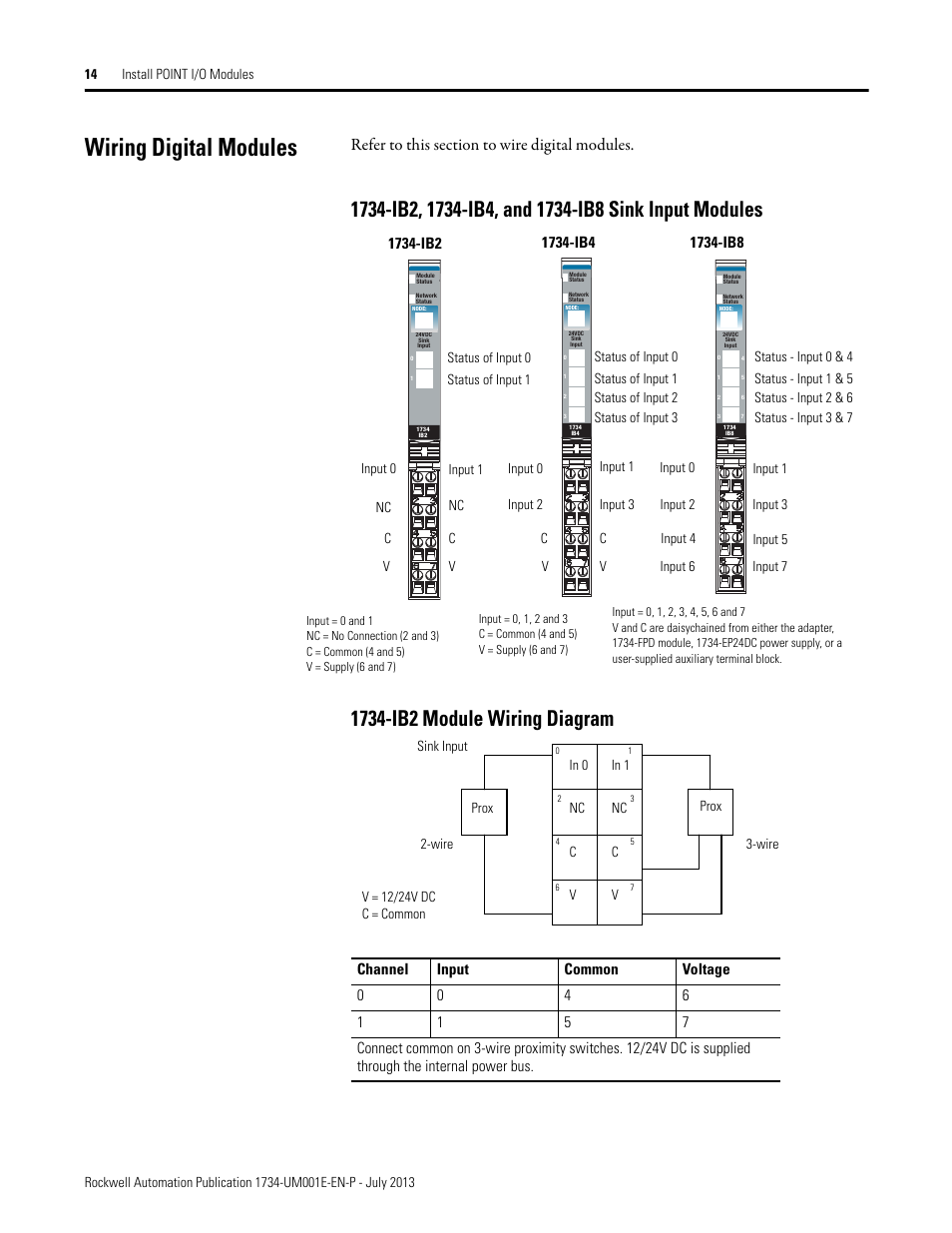
1734-ep24dc wiring diagram. If this equipment is used in a manner not specified by the manufacturer the protection provided by the equipment may be impaired. Database contains 2 Allen-Bradley 1734-EP24DC Manuals available for free online viewing or downloading in PDF. Wire the Module 10 Specifications 13.
We understand your factory floor challenges and can help you meet your goals with one of the broadest safety portfolios in the industry. Wiring Diagram DWG 3-Dimensional. Catalog numbers 1734- OW2 1734-OW4 1734 -OW4K Series C Catalog numbers with the suffix K are conformal coated and their specifications are the same as non-conformal coated catalogs.
This manual is a reference guide for the AENTR AENTR Series B. Wir bieten Notfall Versand und Dropship-Dienste. Our Integrated Architecture.
Kaufen 1734-EP24DC 1734-EP24DC Allen Bradley PowerBus Extension Module Point IO vom Vertreiber Santa Clara Systems. Catalog Numbers 1734-EP24DC 1734-EP24DCK Series B Catalog numbers with the suffix K are conformal coated and their specifications are the same as non-conformal coated catalogs. Allen Bradley 1734-aentr Wiring Diagram.
1734-FPD 1734-FPDK Installation Looking for something else. Rockwell Automation Publication 1734-UM001E-EN-P - July 2013 Preface Purpose of This Manual This manual describes how to install configure and troubleshoot your POINT IO modules. The POINT IO modules in this manual are DeviceNet ready.
Supports 24V DC IO circuits. 1734-EP24DC 1734-EP24DCK 24V DC Installation Download. The 24V DC power for the module is supplied by the internal power bus and originates from the same adapter 1734-FPD module or 1734.
2 Rockwell Automation Publication 1734-IN032E-EN-P - March 2021 POINT IO 4 Channel High Density Current Input Module Installation Instructions ATTENTION. Updated information on wiring POINT Guard IO modules including 1734-IE4S modules 52 Illustrated 1734-IE4S field connections 54 Safety analog-input-module wiring guidelines and examples 59. The examples and diagrams in this manual are included solely for illustrative Faults at the door interlock switch wiring terminals or safety controller will be detected The IB8S input module monitors two door channels and two lock.
Manufacturer Rockwell Automation Brand Allen-Bradley Power Supplies Power Supplies 24V DC PowerBus Extension Module Documents. Safety Guidelines for the Application Installation and Maintenance of Solid-State Controls Publication SGI-11 available from. 2 POINT IO Field Potential Distributor Modules Publication 1734-IN059G-EN-P - December 2018 Important User Information Solid-state equipment has operational characteristics differing from those of electromechanical equipment.
1734 POINT Guard IO system. User Manuals Guides and Specifications for your Allen-Bradley 1734-EP24DC Power Supply. Installation instructions manual.
Common is daisychained from either a 1734 adapter 1734-FPD module 1734-EP24DC power supply or from a user-supplied external terminal block. 1734-OB8 and 1734-OB8E Module Wiring Diagram. Holen Sie sich ein Angebot und wir werden es heute versenden.
1734 Ob8s Wiring Diagram. Topic Page Important User Information 2 Environment and Enclosure 3 North American Hazardous Location Approval 4 European Hazardous Location Approval 5 Prevent Electrostatic Discharge 6 About the Power. Allen-Bradley 1734-EP24DC Manuals User Guides.
Read this document and the documents listed in the Additional Resources section about installation configuration and. Module Wiring Diagram 31538-M The Wiring Base Assembly consists of Mounting Base 1734-MB and Removable Terminal Block 1734-RTB or 1734-RTBS. Connected Device Test Pulse from Connection Schematic Diagram Safety Test Output Category Push Button Connect the push button between 24V.
The examples and diagrams in this manual are included solely for illustrative Allen-Bradley Rockwell Automation ArmorPOINT ControlLogix Logix. Protect your people productivity and environment with our Safety Components and integrated Safety Solutions. Installation Instructions POINT IO 2 and 4 Relay Output Modules Catalog numbers -OW2 successful application and understanding of the product.
1734-TOP 638 g 225 oz 1734-TOP3 792 g 279 oz 1734-TOPS 5568 g 196 oz 1734-TOP3S 668 g 236 oz Wire Size 02525 mm2 2214 AWG solid or stranded copper wire rated at 75 C. On 1734 Ob8s Wiring Diagram. OW4 wiring TB MB ow4 wiring diagram IB8s ie8c wiring connections OW4wiring OW4 EP24DC Text.
24V DC PowerBus Extension Module. Read this document and the documents listed in the Additional Resources section about installation configuration and operation of. 1734-TOP 1734-TOPS 49 x 12 x 144 mm 193 x 047 x 567 in 1734-TOP3 1734-TOP3S 49 x 12 x 168 mm 193 x 047 x 661 in Weight Approx.
Table of Contents Topic Page Important User Information 2 Environment and Enclosure 3 Preventing Electrostatic Discharge 3 North American Hazardous Location Approval 4 European Hazardous Location Approval. Advanced Micro Services. Corrected PCR ID 1230 on wiring diagram connections 9 Updated specifications 12 Updated certifications 13.
Literature Library Find more documentation for Allen-Bradley hardware and FactoryTalk software products. 2 POINT IO Common Terminal Module and Voltage Terminal Module Publication 1734-IN024A-EN-E - March 2005 Important User Information Solid state equipment has operational characteristics differing from those of electromechanical equipment.

1734 Ib4d Modules Rockwell Automation 1734 Xxxx Point I O Digital And Analog Modules And Pointblock I O Modules User Manual Page 34 221

Rockwell Automation 1734 Xxxx Point I O Digital And Analog Modules And Pointblock I O Modules User Manual Page 36 221

Allen Bradley Point I O Ethernet Ip 1734 Aent Installation Instructions Manual Manualzz
Https Www Ideadigitalcontent Com Files 11994 Automation Systems Pdf

Wiring Digital Modules Rockwell Automation 1734 Xxxx Point I O Digital And Analog Modules And Pointblock I O Modules User Manual Page 30 221
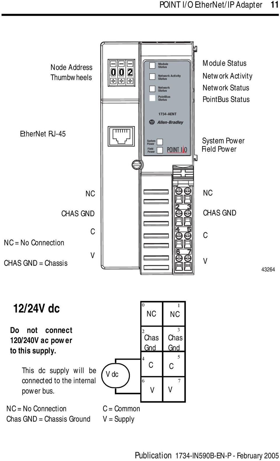
Point I O Ethernet Ip Adapter Pdf Free Download
Http Fs Gongkong Com Files Technicaldata 200801 9 84e2 5da36af71885 Pdf
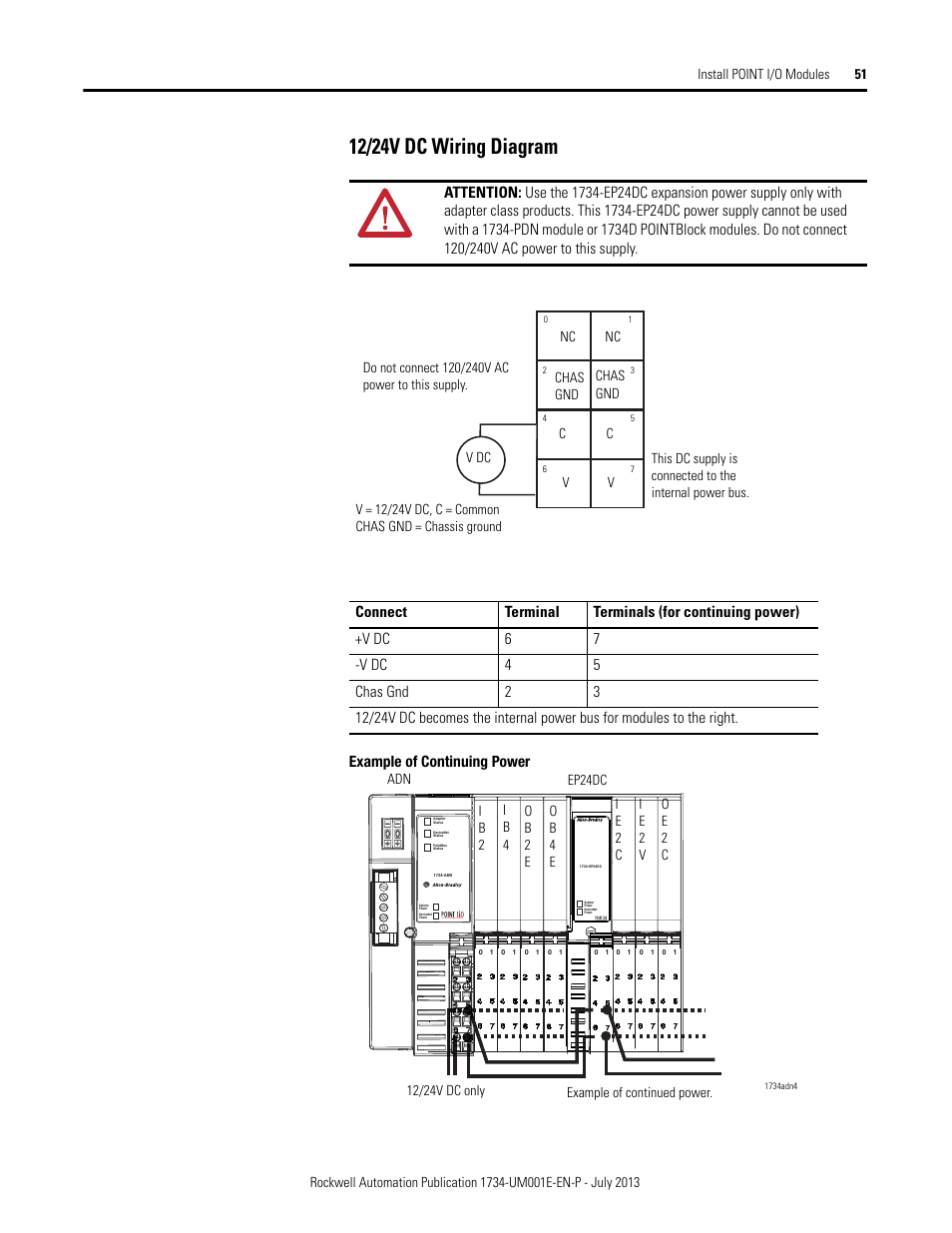
12 24v Dc Wiring Diagram Rockwell Automation 1734 Xxxx Point I O Digital And Analog Modules And Pointblock I O Modules User Manual Page 67 221 Original Mode
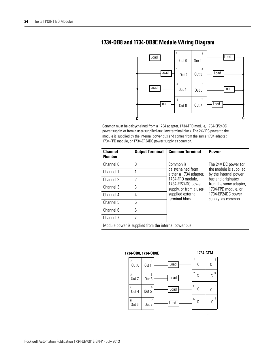
1734 Ob8 And 1734 Ob8e Module Wiring Diagram Rockwell Automation 1734 Xxxx Point I O Digital And Analog Modules And Pointblock I O Modules User Manual Page 40 221 Original Mode
Solved 1734 Top Catalog Block Autodesk Community Autocad Electrical

Point Io 1734 Allen Bradley Input Sensor Hardware Installation Wiring Testing Programming Tutorial
Https Rockwellautomation Custhelp Com Ci Fattach Get 88373
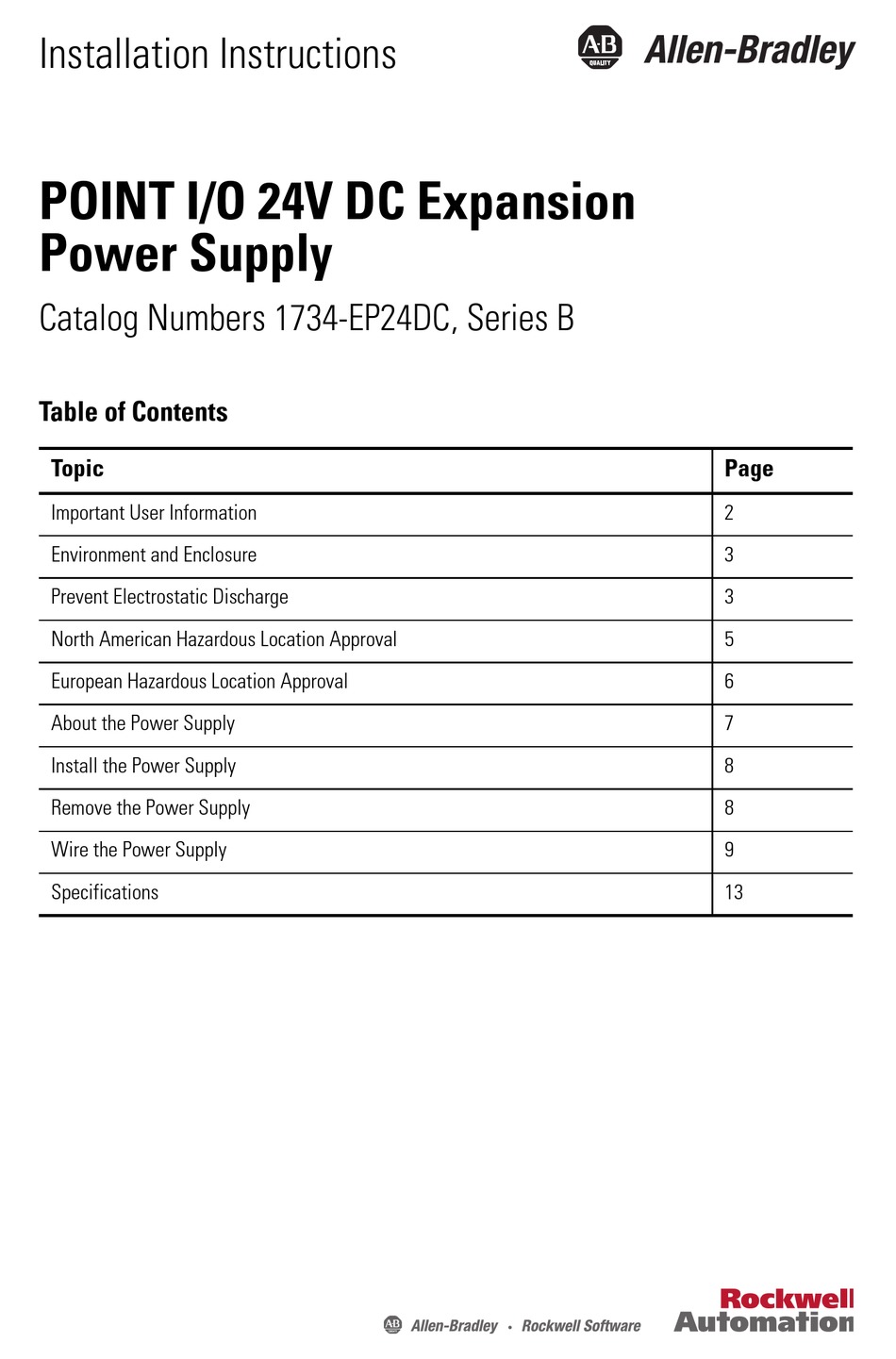
Allen Bradley 1734 Ep24dc Installation Instructions Manual Pdf Download Manualslib
Https Www Ideadigitalcontent Com Files 11994 Automation Systems Pdf
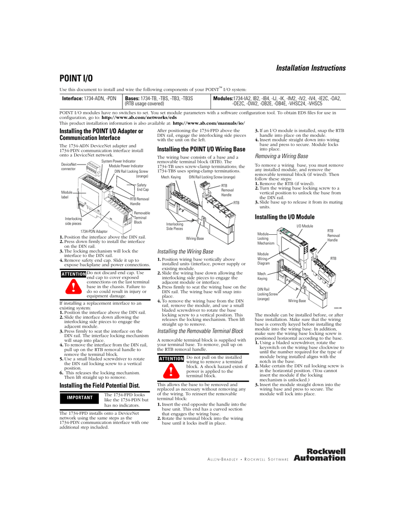
Allen Bradley Point I O 1734 Vhsc5 Installation Instructions Manual Manualzz
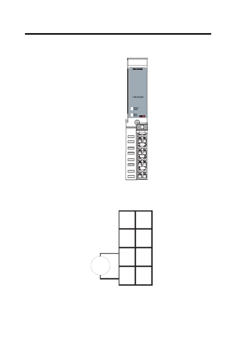
12 24vdc Wiring V Dc Rockwell Automation 1734 Ep24dc Point I O Expansion Power Supply Installation Instructions User Manual Page 12 20
Solved 1734 Top Catalog Block Autodesk Community Autocad Electrical

Point Io 1734 Allen Bradley Input Sensor Hardware Installation Wiring Testing Programming Tutorial


Posting Komentar untuk "1734-ep24dc Wiring Diagram"