12 Volt Dc Motor Circuit Diagram
These circuits are based on 555 Timer. For convenience and safety enclose it in a small metallic cabinet.

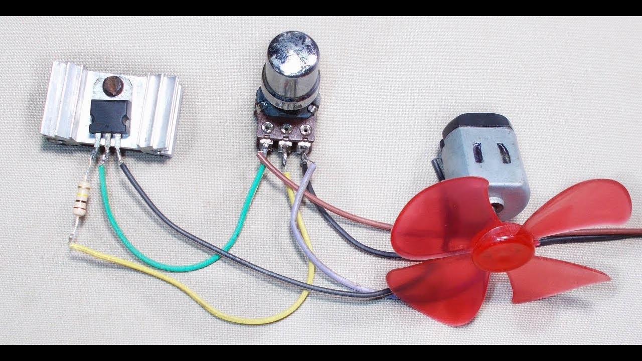
How To Make A Simple Dc Motor Speed Controller Youtube Motor Speed Motor Electric Circuit
Describe how PWM controls DC motor speed.
12 volt dc motor circuit diagram. Ultrasonic sound detector sniffer. First power supply circuit is built with BD139 one zener diode and a few passive components. Control at Frequency 100HZ Adjust.
Hello friends I hope you all will be fine. For Control speed motor 12V 150Wmax 15A. I discuss with you a new idea of DC motor speed control.
12V dc power supply schematics. One trick that I actually use is to printing a similar wiring plan off twice. In previous post we discuss about stepper motor control using Microcontroller and.
Print the wiring diagram off plus use highlighters to trace the circuit. We can adjust the speed of 12V small motor. 12 V Bidirectional Motor Control Schematic Circuit Diagram Admin August 20 2019 0 44 1 minute read This simple circuit drives DC motors with a maximum current of 1 A and can be built with readily available components.
Here are 4 simple 12V power supply circuits with output voltages around 12V. 12 Volt Switching Power Supply circuit diagram and PCB layout. 12V DC motor speed control PWM circuit using TL494.
The voltage can control the speed of DC motor well. One application of the 555 timer Integrated Circuit is the 12V DC motor speed control. PWM 12V dc motor speed controller circuit diagram.
True RMS Watt Meter. Tested At 12v 1A DC FAN use at least 470K POT Vol control. Each of the schematic is very simple to construct and will function without problems if you respect the maximum power supply ratings.
12 Volt Dc Motor Circuit Diagram Posted by Margaret Byrd Posted on June 12 2018 Dc motor sd controller circuit using 3 simple low voltage control 12v diagram detailed ne556 6v. A wiring diagram is a streamlined traditional photographic depiction of an electrical circuit. Types of DC Motors.
A medium size veroboard will do for construction. Wiring Diagram Pics Detail. When you make use of your finger or stick to the circuit with your eyes it may be easy to mistrace the circuit.
Which using a TL494 Switchmode Pulse Width Modulation Control IC is a base for control DC Motor with pulse. Implement a transistor circuit and Arduino program for PWM control of the DC motor. How to make 12 volt DC Motor Speed Controller diyHieverybody today i will show you how to make 12 volt dc motor speed controller very simple make at home do.
The over voltage should be 14V while the under voltage should be 10V. If you want to control the speed of a small 12V DC motor. At 65 volt dc input motor rpm is 0 to 60.
But in practically higher voltage and lower voltage is not that type of possible so in this case we use another type of method which is called PWM better known as pulse width modulation. Even 6V or 9V Motor this can be used too. The circuit diagram of the proposed DC motor speed controller can be seen below.
By using the above 12V DC motor speed control circuit diagram you will have a speed control. They use the principle of PWM motor control mode. When we rotate potentiometer What we change frequency or width of pulse of Gate.
Two transistor FM transmitter circuit diagram and PCB layout. 12v trolling motor wiring diagram Wonderful 24 Volt Trolling Motor Battery Wiring Diagram 3 Prong Wire Diagrams Schematics. Volt or amperes at Drain -Source.
By This Method Smoothly Controlled The Speed Of DC Motor At Negligible Noise. Explain the role of a snubber diode. Finally do not forget to add a suitable heat-sink for transistor T2.
Motor is 12 volt 1 amp. R6 adjust speed motor. A relay could be used for switching the load 12v dc motor on and off.
Many regulators limit the current through the motor which reduces torque. The motor is switched by a darlington with discrete. The motor speed control method.
The circuit diagram for this motor speed controller is very simple and can be built in air without a PCB. These are 12-volt DC variable-speed motor controller circuit using CMOS. Today I share with you a motor control circuit new small project.
Use a good-quality DIP socket for IC1. This speed controller is mainly designed for small 12V motors that do not absorb more than 2A. Basic DC Motor Circuits.
The circuit protects the DC motor from over voltage and under voltage. Simple voltage booster based on Linear Technologies LT1372 includes PCB design. While at 12 volt dc rpm is only 0 to 5.
BY using This Circuit You can control the speed of DC Fan by tuning the Potentiometer volume control variable resistance. When motor is running at full. Here is Some circuit diagram of DC fan Regulator Using PWM Method.
How to get full rpm 60 at 12 volt. The necessary rectification and filtering circuit should be constructed. It is easy and uses a few components that IC digital and transistor driver as main.
A comparator is used to detect if its either high or low. The motor control circuit can be powered by 12V DC supply directly from the vehicles battery. The control circuit is based on a CMOS inverter IC1 type 40106.
DC Motor Learning Objectives. This is a 12V DC motor speed control PWM circuit. Living with the Lab.
DC motor is a purely inductive Load so if you want to control the speed of the DC motor then we have to upper lower the voltage for higher lower speeds. 12 Volt Dc Motor Speed Controller. Driver Motor by Mosfet IRFZ48x 2pcs.

Pwm Controller Circuit Electronic Circuit Projects Electronic Schematics Electronics Circuit

Electrical Page Dc Motor Control Circuit Diagram Circuit Diagram Electrical Circuit Diagram Electronic Circuit Projects
Tutorial Simple Dc Motor Speed Control Circuit How To Make An Universal Dc Motor Speed Controller Youtube Motor Speed Diy Electronics Motor

12v Dc Motor Speed Controler Using Mosfet Irf540 Youtube Motor Speed Electronic Circuit Projects Arduino Motor Control

Pin On Circuit

How To Wire 24 Volt Trolling Motor And 12 Power Pole 2 In Inside Electrical Wiring Diagram Electrical Circuit Diagram Relay

Pin On Narzedzia

Pwm With Forward And Reverse Finally Dc Motor Speed Controller Simple Circuit Electronic Circuit Projects Electronics Circuit Simple Electronic Circuits

Pwm With Forward And Reverse Finally Dc Motor Speed Controller Simple Circuit Electronic Circuit Projects Electronic Circuit Design Electronics Circuit

Pin On

12 Volt Dc Reversing Solenoid Continuous Duty Relays 12 Volt 24 Volt Dc Power Relays Electronic Circuit Design Relay Electronic Circuit Projects
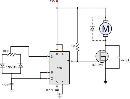
555 Dc Motor Speed Control Motor Speed Circuit Diagram Electronic Circuit Projects

Pin Em Free Electronics Circuits

12 Volt Dc Motor Speed Controller Motor Speed Circuit Diagram Electronic Circuit Projects

12v Dc Power Supply Circuit Diagram Circuit Diagram Circuit Electronics Circuit

How To Build The Simplest Dc Motor Speed Controller Using Potentiometer And Mosfet Updated Motor Speed Circuit Diagram Diy Electrical

How To Build A High Torque Dc Motor Speed Controller Circuit Motor Speed Circuit Diagram Electronic Circuit Design

12v 24v Pwm Motor Controller Circuit Using Tl494 Irf1405 Motor Speed Electronic Circuit Projects Circuit
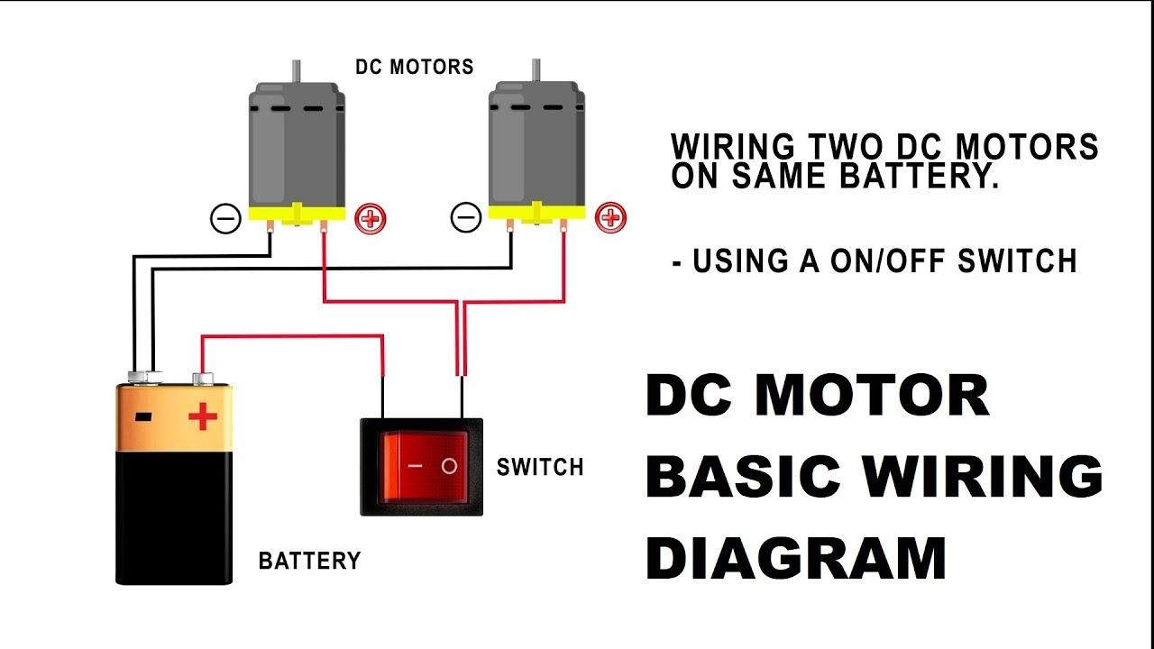
How To Wire A Dc Motor On Battery With Switch And Relay Electrical Symbols Switch Wire Switch
Posting Komentar untuk "12 Volt Dc Motor Circuit Diagram"